AQA GCSE Alternators (Physics)
Alternators
An alternator is a generator that produces an alternating current (ac).
An alternating current is one that changes direction constantly.
Construction of the Alternator
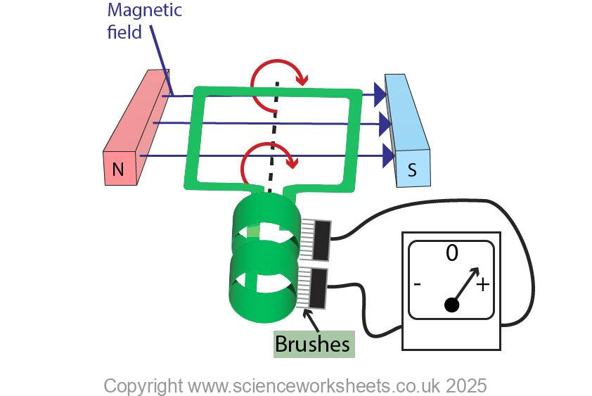
An alternator is made up of a coil of wire which spins in a uniform magnetic field, between two magnetic poles.
Notice in the diagram below that the alternator has SLIP RINGS and not a split ring commutator.
A split ring commutator, is found in an electric motor, not in a generator.
How the alternator works.
The coil turns at a steady speed in one direction only cutting the magnetic field lines when the coil is in the horizontal position. When the coil cuts the magnetic field lines an induced potential difference is induced across the ends of the coil.
Although the coil rotates in one direction only, the induced potential difference will constantly change direction, look at the gif image below and see the needle go from minus to 0 to plus, then back to 0 then back to minus.

Alternators and Graphs
When the coil is horizontal, cutting the field lines there is a maximum potential difference induced. This is known as the peak value for the potential difference. This peak value has been highlighted on the graph for you.
Take note of the labels for both sides of the coil A and B as you work through each of the images below.

The coil is now rotated 90 degrees clockwise as shown in the image below.
The coil is not vertical, so it is not cutting the magnetic field lines. As a result the induced potential difference is now zero volts. This is shown on the graph with the red circle in the image below.

The coil is now rotated a further 90 degrees so it is now 180 degrees from its start position.
You will now notice that A and B have reversed positions compared to first diagram where they appeared. This is to show the coil as 180 degrees compared to the first position.
Notice that a peak induced potential difference is present, but it is in the opposite direction compared to the first graph.

The coil is rotated again by 90 degrees. The coil is now vertical, so it is not cutting the magnetic field lines. As a result the potential difference is 0V.

Increasing the peak value
The size of the peak value of the potential difference can be increased by:
1.Rotating the coil faster
2. Using a stronger magnet
3. Use a coil with a bigger area
4. Using more turns on the coil

Speed of coil rotation
The faster the coil rotates, the greater the frequency of the of alternating potential difference or alternating current.
UK electricity is 50Hz, this means that the coil would rotate at 50 times per second!

When the speed of rotation is increased, both the peak value increases and the frequency increases. So, the graph below will show the true combined effect of this!

Practice Questions
1.What does an alternator do?
2. How is the construction of an alternator different to that of a motor?
3. Describe how a graph of potential difference vs time would change as the coil rotates 360 degrees
Absorption and Emission of EM Radiation
JJ Thomson and Plum pudding model
Ernest Rutherford and the Nuclear Model
Niels Bohr changing the Nuclear Model
Discovering the Proton and Neutron
Measuring radiation from radioactivity
Radiation types and properties
Random nature of radioactive decay
Radioactive contamination or irradiation
Hazards of contamination and irradiation
Studies on the effects of radiation on humans
Different half lives of radioactive isotopes
Nuclear Fission Chain Reaction
Writing nuclear fission equations
Drawing ray diagrams for a concave lens
Drawing Ray Diagram to produce a virtual image for a convex lens
Drawing ray diagram to produce a real image for a convex lens.
Specular and Diffuse Reflection
Seeing Coloured Objects Part 2
Viewing objects through coloured filters
Transparent, Translucent and Opaque