AQA GCSE Resistors(Physics)
A resistor is an electrical circuit component that can affect the size of the current in a circuit.
All components in a circuit have resistance, so any component could be a resistor.
Resistors are either ohmic resistors, so they follow Ohm’s law, or non ohmic resistors so they do not follow Ohm’s law.
Ohm’s Law
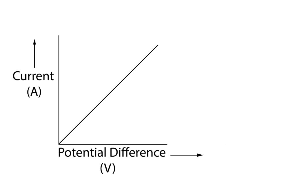
 Ohm’s law states that the current which flows through a resistor (component) is directly proportional to the potential difference across the resistor, providing that the temperature is constant. As shown in the graph.
Testing resistors to find out if they are ohmic conductors.

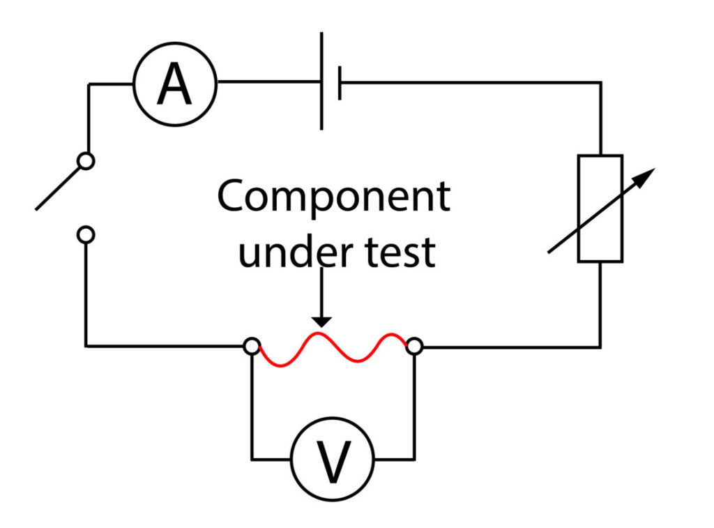
This is a practical that can be used to find out if a conductor is an ohmic conductor. The component under test could be a wire, filament bulb, or diode.
1.Variable resistor is used to set a range of resistance values.
2. At each resistance value, the switch is closed to complete the circuit.
3. The current through the component and potential difference across the component are recorded
4. After each reading has been recorded, the switch is opened to prevent wire overheating
5. A current-potential difference graph is then drawn, if it shows a directly proportional relationship, as shown in the graph above, then the conductor is an ohmic conductor.
The graphs below show the results for a length of wire, bulb and diode

Practice Questions
1.State Ohm’s Law
2. Draw a data table to collect the data for the testing resistors experiment above
3. Describe and explain the current-potential difference graph for a length of wire
4.Describe and explain the current-potential difference graph for a bulb
5. Describe and explain the current-potential difference graph for a diode.
Absorption and Emission of EM Radiation
JJ Thomson and Plum pudding model
Ernest Rutherford and the Nuclear Model
Niels Bohr changing the Nuclear Model
Discovering the Proton and Neutron
Measuring radiation from radioactivity
Radiation types and properties
Random nature of radioactive decay
Radioactive contamination or irradiation
Hazards of contamination and irradiation
Studies on the effects of radiation on humans
Different half lives of radioactive isotopes
Nuclear Fission Chain Reaction
Writing nuclear fission equations
Drawing ray diagrams for a concave lens
Drawing Ray Diagram to produce a virtual image for a convex lens
Drawing ray diagram to produce a real image for a convex lens.
Specular and Diffuse Reflection
Seeing Coloured Objects Part 2
Viewing objects through coloured filters
Transparent, Translucent and Opaque